Hydnet - the specialist in intelligent hydraulic systems
Contact
QCDB

Description

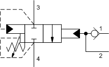
The accumulator sense, pump unload pilot valve is used to sense pressure in an accumulator at port 2 of the valve and when the pressure at port 2 reaches the valve setting, port 3 connects to port 4 to vent a relief valve and unload the pump. This valve has a 20% ratio between unload setting and reset; when pressure at port 2 falls below 80% of the valve setting, port 3 is blocked from port 4 and the pump will come back online to recharge the accumulator.

The integral free-flow check valve is suitable for pump flows up to 15 gpm (60 L/min). For higher capacity pumps, another version of accumulator sense, pump unload cartridge, QPAB, which requires a separate check cartridge is available.

Read more ▼
  • The pressure differential between unload and reset will be within +3/-2% of the stated ratio of the valve.
  • The accumulator sensing area is positively sealed.
  • The spool design of this valve allows it to maintain a fixed differential ratio because the areas are created by diameters on the spool that will not wear or change with use.
  • Minimum clearances between the spool and sleeve and a seal on the pilot piston diameter significantly reduce the potential for silting.
  • When applying this cartridge, a separate drain line is required to prevent erratic operation caused by tank line pressure fluctuations.
  • NOTE: Careful consideration should be given when selecting an adjustment range. System pressure drops and flows tend to affect the operation of unloading valves. Low operating pressures combined with low differentials result in a very narrow band between unload and reset, requiring precise system design. High flow rates typically mean high pressure drops, which subtract from the differential the valve has to work with.
  • Sun has designed a variety of standard accumulator/pump unload assemblies with a variety of features. These assemblies can be found on our website under SOLUTIONS: ACCUMLATOR SENSE, PUMP UNLOAD.
  • Incorporates the Sun floating style construction to minimize the possibility of internal parts binding due to excessive installation torque and/or cavity/cartridge machining variations.

Technical Data

Note: Data may vary by configuration. See CONFIGURATION section.

Cavity T-21A
Series 1
Capacity 15 gpm
Capacity (metric) 60 L/min.
Maximum Operating Pressure 5000 psi
Maximum Operating Pressure (metric) 350 bar
Check Cracking Pressure 4 psi
Check Cracking Pressure (metric) 0,3 bar
Pressure Drop, Port 1 to Port 2 100 psi@15 gpm
Pressure Drop, Port 1 to Port 2 (metric) 7 bar@60 L/min.
Pilot Flow Capacity 46 in³/min.
Pilot Flow Capacity (metric) 0,75 L/min.
Adjustment – No. of CW Turns from Min. to Max. setting 5
Valve Hex Size 7/8 in.
Valve Hex Size (metric) 22,2 mm
Valve Installation Torque 30 – 35 lbf ft
Valve Installation Torque (metric) 41 – 47 Nm
Adjustment Screw Internal Hex Size 5/32 in.
Adjustment Screw Internal Hex Size (metric) 4 mm
Locknut Hex Size 9/16 in.
Locknut Hex Size (metric) 15 mm
Locknut Torque 80 – 90 lbf in.
Locknut Torque (metric) 9 – 10 Nm
Model Weight 0.42 lb.
Model Weight (metric) 0.19 kg.
Seal kit – Cartridge Viton: 990021006

Configuration Options

Control

C Tamper Resistant – Factory Set
L Standard Screw Adjustment
K Handknob

Adjustment Range

A 1000 – 3000 psi (70 – 210 bar), 1000 psi (70 bar) Standard Setting
B 500 – 1500 psi (35 – 105 bar), 500 psi (35 bar) Standard Setting
C 2000 – 5000 psi (140 – 350 bar), 2000 psi (140 bar) Standard Setting
D 250 – 800 psi (18 – 55 bar), 250 psi (18 bar) Standard Setting

Seal Material

N Buna-N
V Viton

Material/Coating

/AP Stainless Steel, Passivated
/LH Mild Steel, Zinc-Nickel
Cavity: T-21A
Nominal Capacity: 20% 15gpm (60lpm)
Downloads
PDFSTP
Possible variants

QCDBCAN, QCDB-CAN, QCDBCAN/AP, QCDB-CAN/AP, QCDBCAV, QCDB-CAV, QCDBCAV/AP, QCDB-CAV/AP, QCDBCBN, QCDB-CBN, QCDBCBN/AP, QCDB-CBN/AP, QCDBCBV, QCDB-CBV, QCDBCBV/AP, QCDB-CBV/AP, QCDBCCN, QCDB-CCN, QCDBCCN/AP, QCDB-CCN/AP, QCDBCCV, QCDB-CCV, QCDBCCV/AP, QCDB-CCV/AP, QCDBCDN, QCDB-CDN, QCDBCDN/AP, QCDB-CDN/AP, QCDBCDV, QCDB-CDV, QCDBCDV/AP, QCDB-CDV/AP, QCDBKAN, QCDB-KAN, QCDBKAV, QCDB-KAV, QCDBKBN, QCDB-KBN, QCDBKBV, QCDB-KBV, QCDBKCN, QCDB-KCN, QCDBKCV, QCDB-KCV, QCDBKDN, QCDB-KDN, QCDBKDV, QCDB-KDV, QCDBLAN, QCDB-LAN, QCDBLAN/AP, QCDB-LAN/AP, QCDBLAN/LH, QCDB-LAN/LH, QCDBLAV, QCDB-LAV, QCDBLAV/AP, QCDB-LAV/AP, QCDBLAV/LH, QCDB-LAV/LH, QCDBLBN, QCDB-LBN, QCDBLBN/AP, QCDB-LBN/AP, QCDBLBN/LH, QCDB-LBN/LH, QCDBLBV, QCDB-LBV, QCDBLBV/AP, QCDB-LBV/AP, QCDBLBV/LH, QCDB-LBV/LH, QCDBLCN, QCDB-LCN, QCDBLCN/AP, QCDB-LCN/AP, QCDBLCN/LH, QCDB-LCN/LH, QCDBLCV, QCDB-LCV, QCDBLCV/AP, QCDB-LCV/AP, QCDBLCV/LH, QCDB-LCV/LH, QCDBLDN, QCDB-LDN, QCDBLDN/AP, QCDB-LDN/AP, QCDBLDN/LH, QCDB-LDN/LH, QCDBLDV, QCDB-LDV, QCDBLDV/AP, QCDB-LDV/AP, QCDBLDV/LH, QCDB-LDV/LH