Hydnet - the specialist in intelligent hydraulic systems
Contact
CBGY

Load holding valve from Sun Hydraulics.

Description

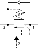
Counterbalance valves with pilot assist are meant to control an overrunning load. The check valve allows free flow from the directional valve (port 2) to the load (port 1) while a direct-acting, pilot-assisted relief valve controls flow from port 1 to port 2. Pilot assist at port 3 lowers the effective setting of the relief valve at a rate determined by the pilot ratio.

Other names for this valve include motion control valve and over-center valve.

Read more ▼
  • Counterbalance valves should be set at least 1.3 times the maximum load induced pressure.
  • Turn adjustment clockwise to decrease setting and release load.
  • Full clockwise setting is less than 200 psi (14 bar).
  • Backpressure at port 2 adds to the effective relief setting at a ratio of 1 plus the pilot ratio times the backpressure.
  • Reseat exceeds 85% of set pressure when the valve is standard set. Settings lower than the standard set pressure may result in lower reseat percentages.
  • Sun counterbalance cartridges can be installed directly into a cavity machined in an actuator housing for added protection and improved stiffness in the circuit.
  • Two check valve cracking pressures are available. Use the 25 psi (1,7 bar) check unless actuator cavitation is a concern.
  • This valve uses orifices to lower the pilot ratio and therefore will pass up to 40 in³/min./1000 psi (0,7 L/min./70 bar) between port 2 and port 3. This is a consideration in master-slave circuits and in the leak testing of valve-cylinder assemblies.
  • All 3-port counterbalance, load control, and pilot-to-open check cartridges are physically interchangeable (i.e. same flow path, same cavity for a given frame size).
  • Incorporates the Sun floating style construction to minimize the possibility of internal parts binding due to excessive installation torque and/or cavity/cartridge machining variations.

Technical Data

Note: Data may vary by configuration. See CONFIGURATION section.

Cavity T-17A
Series 3
Capacity 60 gpm
Capacity (metric) 240 L/min.
Pilot Ratio 2:1
Maximum Recommended Load Pressure at Maximum Setting 3075 psi
Maximum Recommended Load Pressure at Maximum Setting (metric) 215 bar
Maximum Setting 4000 psi
Maximum Setting (metric) 280 bar
Factory Pressure Settings Established at 2 in³/min.
Factory Pressure Settings Established at (metric) 30 cc/min.
Maximum Valve Leakage at Reseat 5 drops/min.
Maximum Valve Leakage at Reseat (metric) 0,3 cc/min.
Adjustment – No. of CCW Turns from Min. to Max. Setting 3.75
Operating Characteristic Standard
Reseat >85% of setting
Valve Hex Size 1 1/4 in.
Valve Hex Size (metric) 31,8 mm
Valve Installation Torque 150 – 160 lbf ft
Valve Installation Torque (metric) 203 – 217 Nm
Adjustment Screw Internal Hex Size 5/32 in.
Adjustment Screw Internal Hex Size (metric) 4 mm
Locknut Hex Size 9/16 in.
Locknut Hex Size (metric) 15 mm
Locknut Torque 80 – 90 lbf in.
Locknut Torque (metric) 9 – 10 Nm
Model Weight 1.36 lb.
Model Weight (metric) 0.62 kg.
Seal kit – Cartridge Viton: 990017006

Configuration Options

Control

C Tamper Resistant – Factory Set
L Standard Screw Adjustment
R Lockwired Screw Adjustment

Functional Setting Range

A 1000 – 4000 psi w/4 psi Check (70 – 280 bar w/ 0,3 bar Check), 3000 psi (210 bar) Standard Setting
B 400 – 1500 psi w/4 psi Check (28 – 105 bar w/ 0,3 bar Check), 1000 psi (70 bar) Standard Setting
H 1000 – 4000 psi w/25 psi Check (70 – 280 bar w/ 1,7 bar Check), 3000 psi (210 bar) Standard Setting
I 400 – 1500 psi w/25 psi Check (28 – 105 bar w/ 1,7 bar Check), 1000 psi (70 bar) Standard Setting

Seal Material

N Buna-N
V Viton

Material/Coating

/AP Stainless Steel, Passivated
/LH Mild Steel, Zinc-Nickel
Cavity: T-17A
Nominal Capacity: 60 gpm ( 240 lpm)
Pilot Ratio: 2:1
Downloads
PDFSTP
Possible variants

CBGYCAN, CBGY-CAN, CBGYCAN/AP, CBGY-CAN/AP, CBGYCAN/LH, CBGY-CAN/LH, CBGYCAV, CBGY-CAV, CBGYCAV/AP, CBGY-CAV/AP, CBGYCAV/LH, CBGY-CAV/LH, CBGYCBN, CBGY-CBN, CBGYCBN/AP, CBGY-CBN/AP, CBGYCBN/LH, CBGY-CBN/LH, CBGYCBV, CBGY-CBV, CBGYCBV/AP, CBGY-CBV/AP, CBGYCBV/LH, CBGY-CBV/LH, CBGYCHN, CBGY-CHN, CBGYCHN/AP, CBGY-CHN/AP, CBGYCHN/LH, CBGY-CHN/LH, CBGYCHV, CBGY-CHV, CBGYCHV/AP, CBGY-CHV/AP, CBGYCHV/LH, CBGY-CHV/LH, CBGYCIN, CBGY-CIN, CBGYCIN/AP, CBGY-CIN/AP, CBGYCIN/LH, CBGY-CIN/LH, CBGYCIV, CBGY-CIV, CBGYCIV/AP, CBGY-CIV/AP, CBGYCIV/LH, CBGY-CIV/LH, CBGYLAN, CBGY-LAN, CBGYLAN/AP, CBGY-LAN/AP, CBGYLAN/LH, CBGY-LAN/LH, CBGYLAV, CBGY-LAV, CBGYLAV/AP, CBGY-LAV/AP, CBGYLAV/LH, CBGY-LAV/LH, CBGYLBN, CBGY-LBN, CBGYLBN/AP, CBGY-LBN/AP, CBGYLBN/LH, CBGY-LBN/LH, CBGYLBV, CBGY-LBV, CBGYLBV/AP, CBGY-LBV/AP, CBGYLBV/LH, CBGY-LBV/LH, CBGYLHN, CBGY-LHN, CBGYLHN/AP, CBGY-LHN/AP, CBGYLHN/LH, CBGY-LHN/LH, CBGYLHV, CBGY-LHV, CBGYLHV/AP, CBGY-LHV/AP, CBGYLHV/LH, CBGY-LHV/LH, CBGYLIN, CBGY-LIN, CBGYLIN/AP, CBGY-LIN/AP, CBGYLIN/LH, CBGY-LIN/LH, CBGYLIV, CBGY-LIV, CBGYLIV/AP, CBGY-LIV/AP, CBGYLIV/LH, CBGY-LIV/LH, CBGYRAN, CBGY-RAN, CBGYRAN/AP, CBGY-RAN/AP, CBGYRAV, CBGY-RAV, CBGYRAV/AP, CBGY-RAV/AP, CBGYRBN, CBGY-RBN, CBGYRBN/AP, CBGY-RBN/AP, CBGYRBV, CBGY-RBV, CBGYRBV/AP, CBGY-RBV/AP, CBGYRHN, CBGY-RHN, CBGYRHN/AP, CBGY-RHN/AP, CBGYRHV, CBGY-RHV, CBGYRHV/AP, CBGY-RHV/AP, CBGYRIN, CBGY-RIN, CBGYRIN/AP, CBGY-RIN/AP, CBGYRIV, CBGY-RIV, CBGYRIV/AP, CBGY-RIV/AP