Hydnet - the specialist in intelligent hydraulic systems
Contact
MWEM

Load holding valve from Sun Hydraulics.

Description

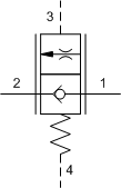
Vented, balanced load control valves combine a balanced modulating element with a reverse flow check. The check valve allows free flow from the directional valve (port 2) to the load (port 1) while the pilot to open modulating element controls flow from port 1 to port 2. Pilot pressure at port 3 determines the flow setting. Backpressure at port 2 does not affect the flow setting because the spring chamber references the vent (port 4).

Read more ▼
  • This valve has no relief function. Not even thermal expansion relief.
  • Maximum valve leakage at reseat for I, K, M ranges is 5 drops/min. (0,3 cc/min.) at 200 psi (14 bar) below cracking pressure; E and G ranges is 3 cubic in/min. (50 cc/min.) at 50 psi (3,5 bar) below cracking pressure; H range is 3 cubic in/min. (50 cc/min.) at 75 psi (5 bar) below cracking pressure.
  • E, G, H ranges are not meant for zero leak type applications.
  • This valve is balanced against load pressures and therefore exhibits self-compensation. Flow is controlled by the pilot pressure. Because of dynamic seals, performance is best in the meter out mode with port 1 being the load and port 2 being tank.
  • All 4-port counterbalance, load control, and pilot-to-open check cartridges are physically interchangeable (i.e. same flow path, same cavity for a given frame size).
  • This valve is a physical replacement for a counterbalance valve but probably won’t work well in a cross-piloted cylinder application. A low pilot ratio is needed for machine stability and a balanced load control has an infinitely high pilot ratio.
  • Applications that use a separate pressure source to the pilot have been successful in providing smooth and stable load control.
  • Sun load control and counterbalance cartridges can be installed directly into a cavity machined in an actuator housing for added protection and improved stiffness in the circuit.
  • This valve has positive seals between all ports.
  • Incorporates the Sun floating style construction to minimize the possibility of internal parts binding due to excessive installation torque and/or cavity/cartridge machining variations.

Technical Data

Note: Data may vary by configuration. See CONFIGURATION section.

Cavity T-22A
Series 2
Capacity 30 gpm
Capacity (metric) 120 L/min.
Maximum Operating Pressure 5000 psi
Maximum Operating Pressure (metric) 350 bar
Maximum Valve Leakage at Reseat See Technical Features
Check Cracking Pressure 25 psi
Check Cracking Pressure (metric) 1,7 bar
Valve Hex Size 1 1/8 in.
Valve Hex Size (metric) 28,6 mm
Valve Installation Torque 45 – 50 lbf ft
Valve Installation Torque (metric) 61 – 68 Nm
Seal kit – Cartridge Viton: 990022006
Model Weight 0.73 lb.
Model Weight (metric) 0.33 kg.

Configuration Options

Control

X Not Adjustable

Minimum Control Pressure

E 75 psi (5 bar)
G 150 psi (10,5 bar)
H 200 psi (14 bar)
I 300 psi (20 bar)
K 450 psi (33 bar)
M 525 psi (36,7 bar)

Seal Material

N Buna-N
V Viton

Material/Coating

/AP Stainless Steel, Passivated
/LH Mild Steel, Zinc-Nickel
Cavity: T-22A
Nominal Capacity: 30 gpm (120 lpm)
Pilot Ratio: Pilot pressure, see leaflet
Downloads
PDFSTP
Possible variants

MWEMXEN, MWEM-XEN, MWEMXEN/AP, MWEM-XEN/AP, MWEMXEN/LH, MWEM-XEN/LH, MWEMXEV, MWEM-XEV, MWEMXEV/AP, MWEM-XEV/AP, MWEMXEV/LH, MWEM-XEV/LH, MWEMXGN, MWEM-XGN, MWEMXGN/AP, MWEM-XGN/AP, MWEMXGN/LH, MWEM-XGN/LH, MWEMXGV/AP, MWEM-XGV/AP, MWEMXGV/LH, MWEM-XGV/LH, MWEMXHN, MWEM-XHN, MWEMXHN/AP, MWEM-XHN/AP, MWEMXHN/LH, MWEM-XHN/LH, MWEMXHV/AP, MWEM-XHV/AP, MWEMXHV/LH, MWEM-XHV/LH, MWEMXIN, MWEM-XIN, MWEMXIV/AP, MWEM-XIV/AP, MWEMXIV/LH, MWEM-XIV/LH, MWEMXKN, MWEM-XKN, MWEMXKN/LH, MWEM-XKN/LH, MWEMXKV, MWEM-XKV, MWEMXKV/AP, MWEM-XKV/AP, MWEMXKV/LH, MWEM-XKV/LH, MWEMXMN, MWEM-XMN, MWEMXMN/AP, MWEM-XMN/AP, MWEMXMN/LH, MWEM-XMN/LH, MWEMXMV, MWEM-XMV, MWEMXMV/AP, MWEM-XMV/AP, MWEMXMV/LH, MWEM-XMV/LH