Hydrostatic drivelines for off-road machines – how to size pump, motor and gearing
Hydrostatic drive is found in almost every mobile off-road machine: forwarders and harvesters, tool carriers, compact loaders, rollers, mining and tunnelling vehicles. The prime mover is usually a diesel engine, but it can just as well be an electric motor. The same principle is also used in industrial and marine applications, for example in winches and other deck machinery, where an electric motor is often the natural choice. The principle is simple, but sizing is what makes a driveline good or bad. Pump, motor, gear ratios and prime mover have to match. Otherwise the machine ends up with too little tractive force, too low a top speed, an engine that stalls on the hill or oil that boils after an hour of driving.
This article shows how we usually lay out and calculate a classic hydrostatic-mechanical driveline for an eight-wheeled off-road machine. All figures in the worked example are typical values chosen to show the method. Your machine will have its own numbers. The worked example is based on a diesel engine. With an electric motor the method is the same, only the power and torque curve looks different. At the end you will find a checklist of the information we need to prepare a first proposal for you.
How the driveline is built
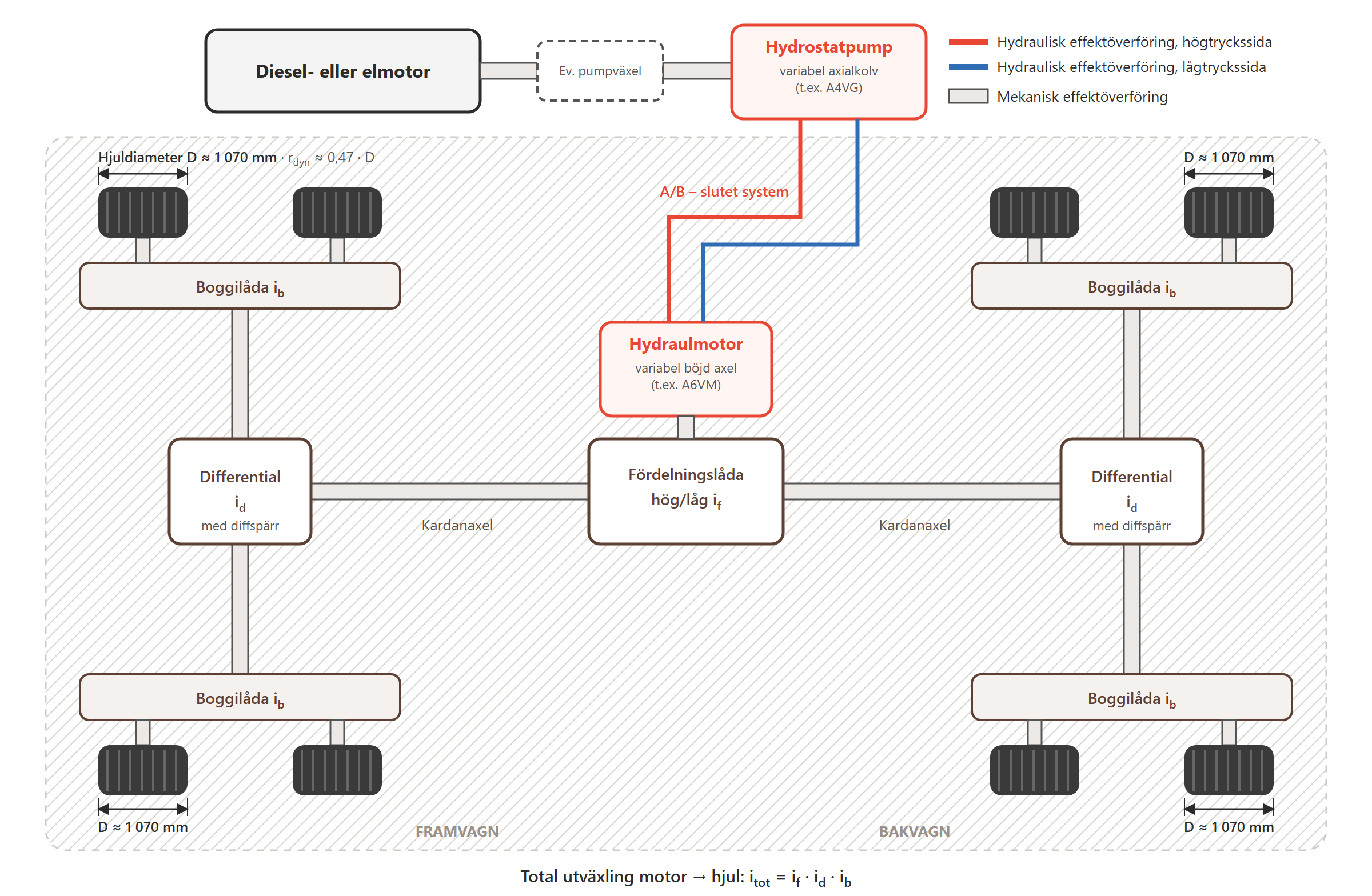
Figure 1. Hydrostatic-mechanical driveline: one pump, one motor and mechanical power transmission to all eight wheels. Red is the high-pressure side and blue the low-pressure side of the closed circuit. The sides swap when the direction of travel is reversed.
The driveline consists of a hydrostatic part and a mechanical part:
Hydrostatic part: pump and motor. The diesel or electric motor drives a variable axial piston pump, the hydrostatic pump, in a closed circuit. The pump supplies oil to a single variable hydraulic motor. This gives stepless speed control in both directions and full tractive force from standstill. If needed, a pump gear can be fitted between the prime mover and the pump, so that the pump speed can be chosen freely relative to the speed of the diesel or electric motor.
Mechanical part: transfer gearbox. The hydraulic motor is flanged to a transfer gearbox, often with two mechanical ranges (high/low). From there, propeller shafts run to the front and rear axles.
Differentials. Power enters the axles through a crown wheel and pinion, normally with a mechanical differential lock.
Bogie boxes. The bogie boxes sit at the outer ends of the axles. Inside, a gear train distributes the drive from the axle to both wheels on the bogie. With two bogie boxes at the front and two at the rear, all eight wheels are driven mechanically and in sync.
The total ratio from hydraulic motor to wheel is the product of the three stages: itot = if · id · ib (transfer box · differential · bogie).
Why one central motor and mechanical distribution?
High efficiency. All power passes through just one pump and one motor. The rest of the way to the wheels is gears, with much lower losses than several hub motors with their hoses and flow dividing.
Mechanical synchronisation. The wheels are forced to keep the same speed relative to each other, especially with the diff locks engaged. A wheel that loses grip cannot spin away, which spares both the ground and the tyres. With individual wheel motors you need flow dividers or electronic anti-slip instead.
Robust and proven. Geared bogie boxes withstand the very high torques that occur when a fully loaded machine climbs over stumps and rocks.
Wheel motors have their advantages: no propeller shafts, free placement and simpler articulated steering. They are a good choice when space is the deciding factor. When efficiency, tractive force and cost matter most, the one-pump-one-motor layout is often hard to beat.
The closed circuit: what keeps the driveline healthy
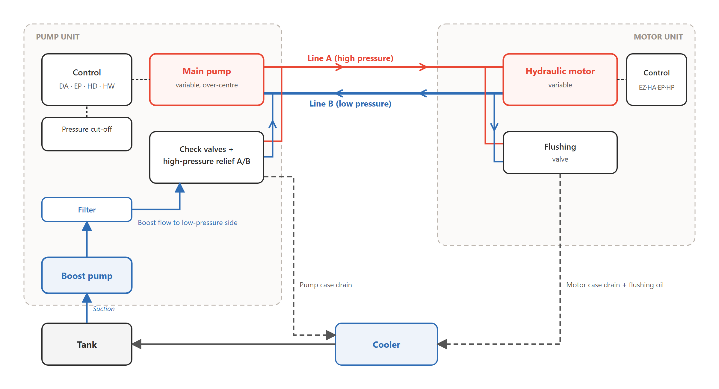
Figure 2. Principle of a closed circuit. Oil circulates between pump and motor. The boost pump replaces what leaks out and is flushed away.
In a closed circuit the main flow circulates between pump and motor (lines A and B). The pump can swivel over centre, so the flow direction, and with it the direction of travel, changes steplessly. A few functions are decisive for service life:
Boost pump and check valves. A boost pump on the pump’s through-drive draws oil from the tank and keeps the low-pressure side pressurised, typically at 20–30 bar. It replaces leakage and prevents cavitation. Boost flow passes through a filter and enters through check valves on whichever side is currently the low-pressure side.
High-pressure relief and pressure cut-off. High-pressure relief valves on the A and B sides protect against pressure peaks. The pressure cut-off destrokes the pump when maximum pressure is reached, so the power is not burned off across the valves.
Flushing valve in the motor. The motor is often several times larger than the pump and runs hot under heavy load. The flushing valve takes a share of hot oil from the low-pressure side through the motor case to the cooler and tank. The boost pump replaces it with cool, filtered oil. Without flushing, the same oil keeps circulating in the loop and gets hotter and hotter.
Cooling and filtration. Case drain from pump and motor, together with the flushing oil, returns to the tank through the cooler. As a rough rule of thumb, 20–25% of the hydrostatic power turns into heat during heavy operation. The cooler is sized accordingly, but only for the driveline’s share if the crane or other functions have their own cooling.
Choosing pump and motor
A common and well-proven choice in this power class is a variable axial piston pump for closed circuits, for example Bosch Rexroth A4VG, combined with a variable bent-axis motor, for example A6VM. Equivalent units are available from several manufacturers. The principles below apply largely regardless of brand, with one exception: the DA control is a Rexroth-specific function.
Pump control
DA, speed-related control (automotive). Pump displacement follows the engine speed. The throttle pedal becomes the drive pedal, much like in a car, and the pump automatically destrokes when the engine is pulled down. This gives natural stall protection. It is simple and robust and needs no electronics. Note that DA is a special feature of Rexroth drivelines and is not available from other manufacturers. To get the same drive behaviour with another brand, it has to be done electronically with EP and a controller.
EP, electro-proportional control. Displacement is set by a current signal from a controller. This gives full freedom to program drive behaviour, ramps, cruise control, eco mode and load-dependent speed limiting. It requires a controller and software.
HD and HW, hydraulic proportional control by pilot pressure and by mechanical lever respectively. These are used when the system should stay fully hydraulic.
Motor control
EZ, electric two-position control. Two fixed positions, for example maximum displacement for tractive force and minimum displacement for transport speed. Distinct and simple.
HA, high-pressure automatic. The motor adjusts itself to the working pressure. High pressure gives large displacement and more torque. Low pressure gives small displacement and higher speed. Many versions have an electric or hydraulic override that locks the motor at maximum displacement. This gives maximum engine braking downhill and full torque for precision driving.
EP and HP, electrically and hydraulically proportional control, when the motor is to be controlled steplessly from a controller or a pilot pressure.
Pump/motor size ratio
Combining a small pump with a much larger motor (for example a 56 cm³ pump and a 160–200 cm³ motor, a ratio of roughly 1:3 to 1:3.5) gives high starting torque from a small, cost-effective pump. The price is lower motor speed per litre of oil and more heat in the motor case. That is why a flushing valve in the motor is practically mandatory in this combination. A larger motor (200 instead of 160 cm³) gives 25% more torque at the same pressure. The transfer box can then have a lower ratio, but top speed per litre of oil drops.
Worked example with typical values
The example is an eight-wheeled off-road machine in the 55 kW class, roughly the size of a small forwarder. The values are chosen to show the method and do not refer to any specific machine.
Input
Typical value
Kerb weight + payload
7,000 + 7,000 kg = 14,000 kg
Diesel engine
55 kW at 2,200 rpm (≈ 240 Nm). About 5 kW goes to fan, steering, etc.
Wheels
Outer diameter approx. 1,070 mm (e.g. 550/45-22.5), dynamic rolling radius 0.50 m
Axles
Differential 4:1 × bogie 5:1 = 20:1
Pump
56 cm³/rev, driven directly by the engine
Motor
160 cm³/rev, minimum displacement set to 45 cm³
Pressure
400 bar high pressure, 25 bar boost pressure, Δp = 375 bar
Transfer box
Low 2.5:1 · high 1.0:1
Targets
Tractive force ≈ traction limit (μ ≈ 0.6 → 82 kN), transport speed approx. 24 km/h
Motor torque at maximum displacement: T = Vg · Δp / (20π) · ηhm = 160 · 375 / 62.8 · 0.94 ≈ 898 Nm.
Step 2: Tractive force in low range
Torque at the wheels = 898 Nm · 2.5 · 0.97 · 20 · 0.92 ≈ 40,050 Nm. Tractive force is 40,050 / 0.50 ≈ 80 kN, just below the traction limit. That is exactly where you want to be. More hydraulic tractive force than the tyres can transmit only gives wheel spin and wear.
Step 3: The power limit, the most important insight
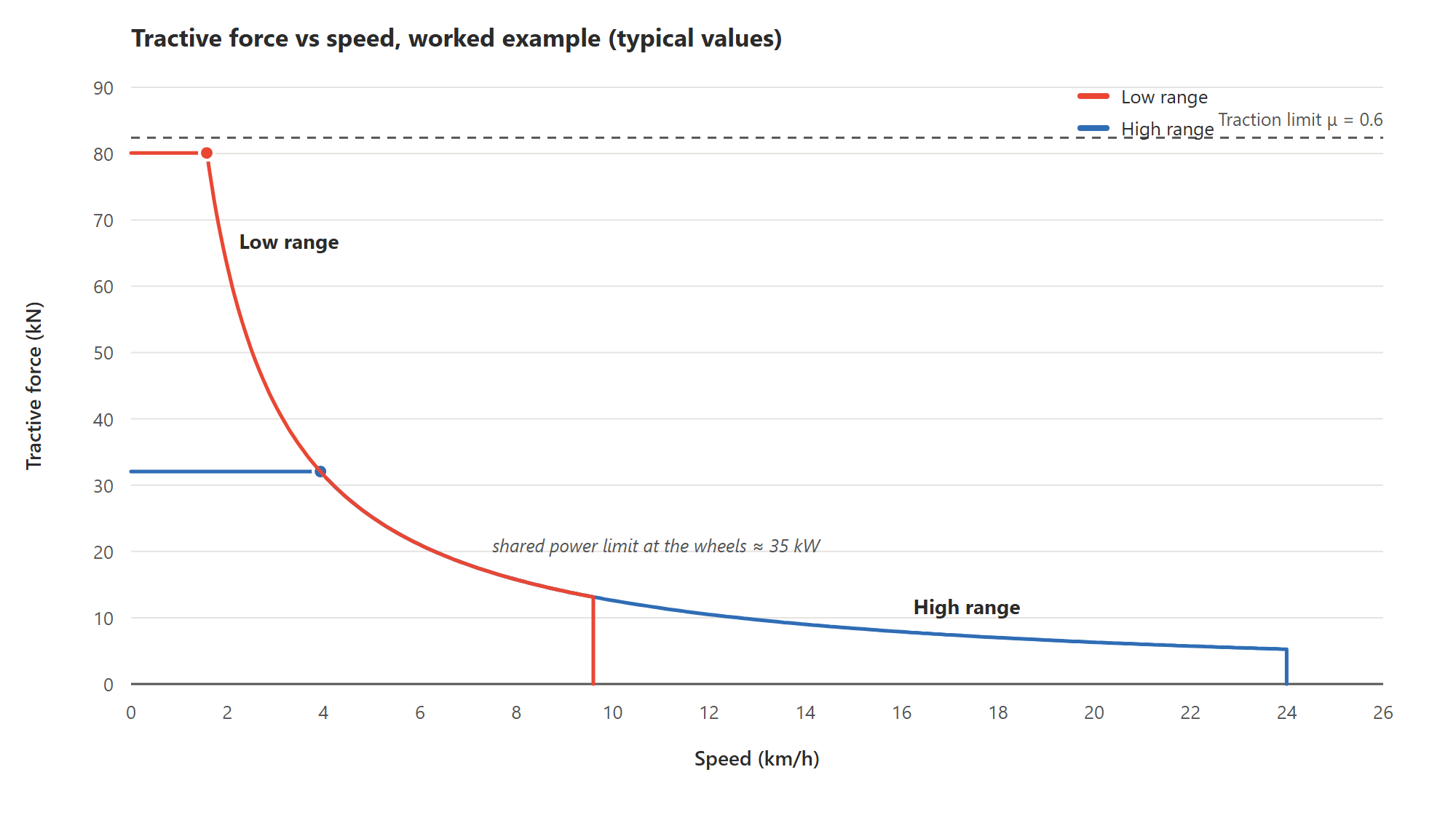
At 375 bar and 115 l/min the pump would need about 72 kW of hydraulic power and over 350 Nm from the engine, which only has 55 kW and 240 Nm. Full tractive force is therefore available only at creep speed, up to about 1.6 km/h. Above that, pump control has to limit the power. With about 50 kW available and 70% overall efficiency from engine shaft to wheel, about 35 kW remains at the wheels. That is the hyperbola you see in Figure 3.
This is where many first drafts fail. If the pump has no power- or speed-related limiting (DA, or electronic anti-stall with EP), the engine will be pulled down and stall as soon as the machine pulls hard.
Step 4: Speed and gear ranges
In low range at full motor displacement the speed is about 2.7 km/h. As the motor then destrokes to 45 cm³, the speed rises to about 10 km/h. In high range (1.0:1) the same flow gives about 24 km/h, with the motor and the propeller shafts at about 2,550 rpm. High range still gives about 32 kN of tractive force, which is plenty for transport driving.
Why are two ranges needed? The machine has to run at full power from about 1.6 km/h (full tractive force) up to 24 km/h, a conversion range of about 15 times. A hydrostat with variable pump and variable motor covers about 6 times in this example. The mechanical high/low range (2.5 / 1.0 = 2.5) covers the rest. That is why almost all off-road machines of this type have a two-speed transfer box. The alternative is to accept a lower top speed or less tractive force.
Figure 3. Tractive force versus speed in the worked example. The flat part is limited by maximum pressure and the curved part by engine power. Low range covers off-road work and high range covers transport.
Step 5: Check the limits
Motor speed against the data sheet limit at the actual displacement. A variable motor normally tolerates higher speed at reduced displacement than at full displacement.
Propeller shaft and axle limits. Maximum speed and continuous and intermittent torque from the axle and bogie supplier.
Braking. In a closed circuit the hydrostat brakes when the pump destrokes. The braking power is then absorbed by the diesel engine, whose engine braking is limited. On long downhill runs with full load you need to check that the engine does not overspeed. Solutions include locking the motor at maximum displacement, using gentle ramps and, if needed, an additional service brake.
Heat. With about 20–25% loss of 50 kW, the driveline’s cooling demand is about 10–12 kW during heavy operation.
How we have solved this in previous projects
We have supplied this type of driveline to manufacturers of compact off-road machines, from the first sketches to prototype units. A few lessons learned:
Electronic pump control in the prototype phase. In one project we chose an electro-proportionally controlled pump (EP) and a motor with hydraulic displacement control. The customer could then tune the drive behaviour in software on the prototype before the series configuration was frozen. Changing the control option on a pump afterwards costs more than changing a parameter.
The transfer box ratio is the free variable. Axles and bogie boxes are often given by a sub-supplier. The transfer box and an optional pump gear are where you can adjust so that pump and motor operate in their best ranges.
Budget prices for both prototype and series. The choice of concept is often decided by the series cost. That is why we like to price both levels straight away, so the concept can be assessed financially before the solution is studied in detail.
Plan for lead time. Custom-configured axial piston units often have a much longer lead time than standard stocked versions. Order prototype units early.
What we need from you for a first proposal
With the information below we can prepare a first proposal with a schematic, component selection with type codes, a calculated tractive force curve and a budget price. Not everything has to be exact. Estimates are fine at this stage, and we are happy to help fill in the gaps.
Machine and operation
Machine type and application (e.g. forwarder, tool carrier, mining vehicle)
Kerb weight and maximum payload, or total weight
Number of driven wheels/axles and type of suspension (bogie, rigid axles, articulated steering)
Wheel outer diameter or dynamic rolling radius, and tyre type
Desired top speed for transport and desired speed in working mode
Desired maximum tractive force, or maximum gradient and type of ground
Duty cycle: share of time in heavy operation, transport and idling
Power source
Power and torque curve of the diesel engine or electric motor (or make and model)
Idle and rated speed, and direction of rotation
Pump connection: SAE flange, coupling, optional pump gear or PTO
Other hydraulic functions on the same pump (crane, steering, fan) and their power demand
Mechanics
Ratios in axles, differentials and bogie boxes or hub reductions
Whether a transfer box or gearbox exists, or whether the ratio is to be developed (high/low?)
Maximum permitted speed and torque, continuous and intermittent, on propeller shafts and axles
Available space and mounting position for pump and motor
Control and functions
Desired drive feel: pedal and car-like driving (automotive), joystick or fully electronic control
Existing control system (CAN/J1939, own controller), or whether you would like us to propose one
Oil type, tank volume and existing cooling/filtration
Service life requirement (operating hours) and any special requirements or standards
Volume and schedule
Number of prototypes and when they are needed
Expected series volume per year and planned start of series production
Any requests for specific products
What you get back
Once we have the information, we come back with a first proposal that includes:
a schematic of the driveline
proposed pump, motor and controls with type codes
calculated tractive force and speed per gear range, checked against the engine and mechanical limits
budget prices for prototype and series volumes
an estimate of lead time.
From there we take it further together: detailed sizing, valves and controls, prototype delivery and commissioning.
Do you have a machine on the drawing board? Send us the information above. A hand sketch with a few numbers on it is just as good, and that is often how the best projects start. You can also ask Pascal directly here on the site.
A standard counterbalance valve is always a compromise between stability and efficiency. High pilot ratios are chosen for efficiency, while low pilot ratios provide better stability. Unnecessary energy consumption when…
Designing hydraulic manifolds is our core expertise – we’ve made thousands over the years. A well-executed design always starts with the right methodology and clear priorities. There are many guidelines,…
With ACE Controls hydraulic dampers, the braking force can be adjusted for both the inward and outward movement. These dampers are used to control, slow down, and synchronize swinging and…
The new patented FREP valve combines electrically proportional variable throttling with a compensator in a single unit. This allows for a constant priority flow regardless of variations in load pressure.…