FREL – Fully Adjustable Priority Valve
How a Priority Flow Control Valve Works A priority flow control valve supplies the main function with a fixed, pre-set flow rate, while the remaining flow can be used for…

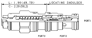
A load holding valve keeps a hydraulic load securely in place and prevents it from moving in an uncontrolled way if system pressure is lost — for example due to a burst hose, a valve closing, or a pump stopping. Other names for the same function are overcenter valve, counterbalance valve and load holding valve. This valve type is central to any application where an overrunning load, a cylinder or a hydraulic motor must be held safely without the drive system being actively pressurized: cranes, presses, lifts, drilling equipment and rotating drives.
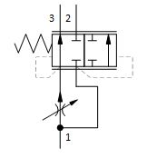
A counterbalance valve combines two functions in a single cartridge. A check valve allows free flow from the directional valve (port 2) to the load (port 1) when the load is being driven. In the opposite direction — when the load tries to run away on its own — flow from port 1 to port 2 is held back by a direct-acting relief valve. That relief function is pilot-assisted: pilot pressure at port 3 (normally taken from the opposite side of the cylinder or motor) lowers the effective setting by a ratio determined by the pilot area. As long as the directional valve is in neutral, the relief function holds the load still; as soon as the directional valve opens for lowering or rotation, pilot pressure follows along and the valve opens smoothly in step with the load.
A few practical reference points: set the counterbalance valve to at least 1.3 times the maximum load-induced pressure, expect the fully clockwise (minimum) setting to be below 14 bar (200 psi), and note that reseating occurs at a minimum of 85% of the set pressure in the standard configuration. Back pressure at port 2 raises the effective setting further — by a factor of (1 + pilot ratio) times the back pressure — which is worth accounting for in circuits with series-connected functions.
Sun Hydraulics also makes a simpler alternative: the pilot-operated check valve (POCV), without a relief function or an adjustment screw. It opens outright once pilot pressure exceeds a threshold, without metering or throttling the load on the way. The choice between the two is rarely a close call:
A practical benefit: in most frame sizes, 3-port counterbalance, load holding and pilot-operated check valve cartridges are physically interchangeable — same flow path, same cavity — which makes it easy to upgrade an existing design without new manifold machining.
Standard counterbalance valves work well with a fairly constant load, but become inefficient — or even unstable — when the load or flow varies significantly, for example in hydraulic motors or rotating drives. Sun Hydraulics has three specialty series for that type of application:
A rule-of-thumb signal to listen for: if the application has a wide flow range (for example 50–500 lpm), a varying load pressure, or feels jerky and inefficient with a standard valve, it’s time to look at one of the three.
Not sure which counterbalance valve suits your application? All our load holding valves are described with full technical data on their respective product pages — see for example the CBCA family. And feel free to get in touch, or ask Pascal right here on the site.